Building an autonomous light finder robot
ArticleCategory: [Choose a category, translators: do not
translate this, see list below for available categories]
Hardware
AuthorImage:[Here we need a little image from you]
![[Photo of the Authors]](../../common/images/KatjaAndGuido.jpg)
TranslationInfo:[Author + translation history. mailto: or
http://homepage]
original in en Katja and Guido
Socher
AboutTheAuthor:[A small biography about the author]
Katja is the German editor of LinuxFocus. She likes Tux,
computer graphics, film & photography and the sea. Her homepage can be found
here.
Guido is a long time Linux fan and he likes Linux because it
gives you choices and freedom. You can choose and develop
solutions according to your needs.
Abstract:[Here you write a little summary]
In this article we describe how to build an autonomous robot with a
microcontroller that will always try to walk to the brightest spot.
ArticleIllustration:[One image that will end up at the top
of the article]
![[Illustration]](../../common/images/article297/robot.jpg)
ArticleBody:[The main part of the article]
Introduction
Two years ago we presented a "Linux-controlled walking
robot" in LinuxFocus.
It was very special in its design as it walked on legs and had
no conventional motors. This was a very interesting aspect of
this robot, however it was very slow, needed a lot of current
and required a lot of special parts and skills to build it.
The design of our new robot is very different. It is cheap
and you will be able to build it from parts that are available
almost everywhere around the world. It is an autonomous robot controlled
by an AVR microcontroller. As an autonomous robot (not controlled
by a person) we programmed it to run towards the brightest spot in the room.
The mechanics
![[conrad motor]](../../common/images/article297/297_conrad.jpg)
The small gear motor from conrad
|
![[servo motor]](../../common/images/article297/297_servo.jpg)
A standard servo modified to work as a motor. This is probably the best
solution but we had this idea only after the robot was already built.
|
The robot has only 2 wheels which are driven by 2 independent motors. The
third wheel is a ping-pong ball. This enables the robot to turn on
the spot. We have used rubber wheels from toys but you don't have
to dismantle yours too. The top of a marmalade jar with a rubber band
around also makes for a very nice wheel.
For an autonomous robot it is obviously important that it can
operate from batteries. Since the microcontroller runs with 4.5V the
motors also must work with 3-4.5V. They must also not take too much
current otherwise the batteries and the control circuit will get too big and
heavy. For this design we use an integrated motor driver chip, called l293d.
The l293d motor driver chip can drive peak loads up to 0.5A. The
motors should therefore need less than 0.5A under worst conditions.
We used 2 small gear-box motors from Conrad (www.conrad.de, part
number: 242802) but you can also use any other small motor with
a gear-box. In fact we think now that the best solution would have been
to use standard Servo Motors as used for the remote control of small
boats, cars or planes.
Normally these Servo Motors can turn only a certain angle
but you can open the gear box of the Servo, take out the stopper,
remove the potentiometer and the electronic. It's a perfect small but
strong motor and Servos are easy to get.
![[motor on wooden board 1]](../../common/images/article297/297_mecanics1.jpg)
To build the robot mount the motors under a small wooden board (12cm x 9cm)
and position them almost in the middle such that most of the load will
be on the two axis. The third wheel, the ping pong ball, must take
only a small fraction of the weight of the robot to ensure that it can
slide nicely in its "bearing" (see pictures).
![[motor on wooden board 1]](../../common/images/article297/297_mecanics2.jpg)
The bearing for the ping pong ball is the top of a small plastic bottle which happened to have
exactly the
right size.
![[pill box]](../../common/images/article297/297_mecanics3.jpg)
For the operation of the robot we have used 3 AAA batteries. Position
the battery holders as shown below. The batteries are quite heavy so
take care that most of the load is on the wheels and only a little bit
on the ping pong ball. You can place a switch to power on/off the robot
somewhere on the side.
![[position of the batteries]](../../common/images/article297/batteries.gif)
Sensors
We give our robot 2 types of sensors:
- touch sensors: this way the robot knows if it has hit an object
- light sensors: for the robot to find the brightest spot
in the room
The touch sensors are simple switches made out of steel wire. We bend
them as shown in the picture below:
![[steel wire]](../../common/images/article297/steelwire.jpg)
There are 4 touch sensors mounted with a screw on the corners of the
wooden board.
When the robot hits an object then the steel wire (2, see picture below) touches the
second wire on the board (3) and this closes the electrical connection
between steel wire and wire on the wooden board.
To prevent that the steel wire bends off when the ping pong ball is
not in its bearing we have added a small wooden post (1) under the board. This
post must be about 5 mm above ground when the ping pong ball is in the
bearing.
The steel wire should end about 5-7mm above ground.
![[touch sensors]](../../common/images/article297/touchsensor.jpg)
The light sensors are 3 photo resistors. We placed card
board between the photo resistors as shown in
the picture below. This card board creates
shadows on the resistors when the light comes from the side. Only when the
light comes exactly from the top it will provide for an equal amount of light on
all 3 sensors. Comparing the values of the 3 sensors the robot can
decide in which direction to go.
You can solder the 3 photo resistors on a small experimentation board
(those boards with a lot of holes) and fix the whole thing with a single
screw on the robot.
How to connect the sensors and the two motors to the printed circuit board
with the microcontroller will be explained further down. Now that the
mechanical parts are done let's have a look at the "brain" of the robot.
The Circuit
We use an AT90S4433 microcontroller as the "brain" of our robot but
the "brain" can't directly deliver enough power to drive the motors.
This is where the L293D motor driver chip comes into the picture.
This chip contains 4 digital
output amplifier stages with extra protection diodes to protect
against high voltages induced by the coils of a motor. 2 of the output
stages can be used to drive one motor. This way it is possible to
let the motor turn left or right.
We put one motor between output 1 and output 2 and the other between
output 3 and output 4. The enable pins of the chip can be used
to control the speed of the motors when we send pulses of variable length
to the enable pins.
The rest of the circuit is very simple: We use the Atmel AT90S4433
microcontroller again. You know this microcontroller already from previous
LinuxFocus articles. Its analog inputs can be used to measure the light
on the photo resistors and the touch sensors can be connected directly
to the digital input lines as shown below.
More information about the details of the microcontroller can be found
in Guido's March 2002 article: Programming
the AVR Microcontroller with GCC.
The circuit works with 4.5V. Three AAA batteries are therefore enough to
operate the robot.
Now the circuit for our autonomous robot would be ready. However what do
you do if the robot does not work as expected because something is
going wrong in the software? You can't see anything. You don't know
what the values of the light sensors are, you don't know why the robot software
has taken this or that decision. What we need is some kind of output
screen or display to understand what the robot does. The RS232 serial line
is well suited for this purpose. We can print values of variables
and we could even communicate with the robot. We don't want to connect
it all the time but we need it to debug the robot. It therefore makes
sense to put the max232 and other parts needed for the RS232 connection
onto a separate board and connect it only when needed:
The complete Eagle circuit diagrams and board layouts can be downloaded
at the end of the article together with the software for this robot.
We don't describe the board layout here. You can see it in eagle. The circuit board is small
enough
to fit between the batteries.
Below is a drawing where you can see which touch sensor on which side
of the robot is connected to which pin in the circuit diagram.
The drawing also shows how to connect the motors. The polarity of the
motors is chosen such that the robot would move forward (in the
direction of the arrow) if +3V would be connected to the "+"-pin and GND
to the "-"-pin. 1y to 4y are the names of the pins on the l293d.
![[]](../../common/images/article297/robot_connectors.gif)
The Software
We don't want to go into a lot of details here. The main program can
be found in the file linuxrobot.c (download of the software at the
end of the article). The program includes a lot of comments and
should be easy to read for a C programmer. The main loop first checks
the analog values of the photo-resistors by running the
Microcontroller's internal analog to digital converter in
single shot conversion mode 3 times. After that the touch sensors
are checked. If any of these touch sensors is pressed then
they take preference over the light sensors because it
probably hit some obstacle. The robot will turn the motor
a few milliseconds in the opposite direction of the touch sensor which was hit.
If no touch sensor was hit then the photo sensors are compared with
each other. This comparison is done in the function compare_with_tol()
where we compare one value against a mean value of two. To avoid
that we are affected too much by "noise" we say that 2 values are equal
if the difference is less than 5 percent.
Based on the comparison of the photo sensors we can then decide which
motor to turn. Since we have only 2 wheels we can turn the robot on the
spot by turning one of the wheels faster or even
turning them in opposite direction. Since the microcontroller repeats
the measurement very fast several times per second the movement of the
robot looks as if it continues even if we stop one motor for a
fraction
of a second in order to turn a bit left or right.
Putting it together
When you assemble the electronics it is always a good idea to test
it in steps. This way you can easily narrow down possible faults.
There are 3 different test programs included in the linuxrobot software
package (download at the end of the article).
The program ledtest causes the 2 LEDs to blink. You load it with
the command "make ledtestload". This will compile the program and load
it to the microcontroller. The 2 LEDs should start to blink immediately
after the program was loaded. When this test is successful you can
be sure that the microcontroller with its oscillator and the connection
to the PC for loading software does work.
Next is the motortest program. This test program implements "an electronic rubber
ball". You load it with the command "make motortestload". The motortest
program checks the touch sensors all the time and if one of them is
hit then the robot moves away from the sensor that was hit. If you hit
the robot with your hand on one side then it will bounce back. Put
your second hand behind the robot and it will bounce back and forth
between your 2 hands like a rubber ball. If the robot passes this
test then everything except the light sensors and the RS232 connection
is tested.
The final test program is called adctest (compile and load with
make adctestload). The program tests the RS232 connection which
is there to debug the robot and it tests the ADC (analog to
digital converter) with the 3 photo resistors.
Load the program into the microcontroller and then connect the
adapter for the RS232 connection to your PC. After that run
the following 3 commands in a shell:
make ttydevinit
./ttydevinit /dev/ttyS0
cat /dev/ttyS0
The robot should periodically print the values of the light
intensity it has measured with the photo sensors.
When all the tests are passed you can load the final program
into the robot with "make load".
The best playground for the first tests is a room with
just a single lamp in the middle. The robot should just run
straight in the direction of the lamp and stop there.
It is quite fun to see how it turns around if you put it on
the ground with its back facing to the light source or how it
avoids shades.
Problems and improvements
We started this robot as a little experiment. It was
good fun to build an autonomous robot which can make decisions
on its own and does not need any data connection to a PC.
The program included in the linuxrobot package which you can
download further down in the article is still small and simple
but does what we wanted: The robot runs to the brightest spot.
We would like to mention a few things that could be used as a starting point
for further development:
- The touch sensors are only checked in rather large intervals (few ms)
which limits the responsiveness of the robot. They should be checked
more often.
- If one of the touch sensors was hit then this takes priority over
all other things and the robot moves for a few hundred milliseconds
in the opposite direction. If a different sensor hits during this time
then this is currently ignored.
- The sensitivity of the photo resistors decreases in poor light
conditions.
This can lead to the effect that the difference measured
between the sensors is below the threshold which is hardcoded
in the program (5%) and the robot thinks that all sensors get equal amount of
light. The light values that come out of the ADC could be adjusted
by a non linear filter curve to compensate this effect.
At the moment the linuxrobot program is small and simple so you should be able to understand
it and maybe develop it further. It needs only 50% of
the memory of the 4433 microcontroller so you can still add a lot
of things.
The good thing about this robot is that the hardware is somehow generic:
It's basically 2 motors and some sensors attached to a microcontroller.
All the logic is implemented in the software. That means by changing the
software you can change almost everything as you like.
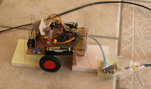
Here is a picture of the robot in test position. We put some post-it paper
block under it so it does not run away. The rs232 line is connected
for debug purposes:
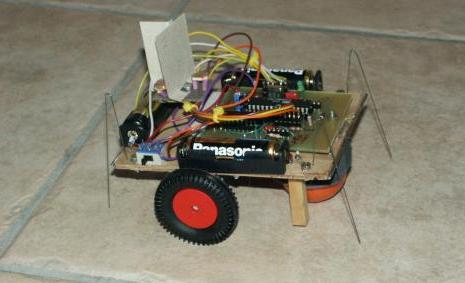
... and the final robot searching for light....:
References
![[photo sensors]](../../common/images/article297/lightsensors.jpg)
![[position of the photo sensors]](../../common/images/article297/sensors.gif)